Cemline chilled water buffer tanks cwb are designed to be used with chillers which do not have water volumes of sufficient size in relation to the chiller.
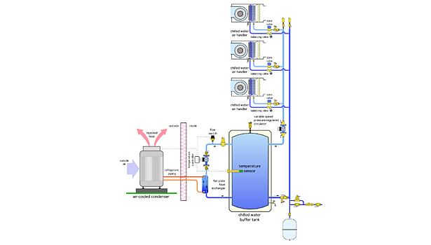
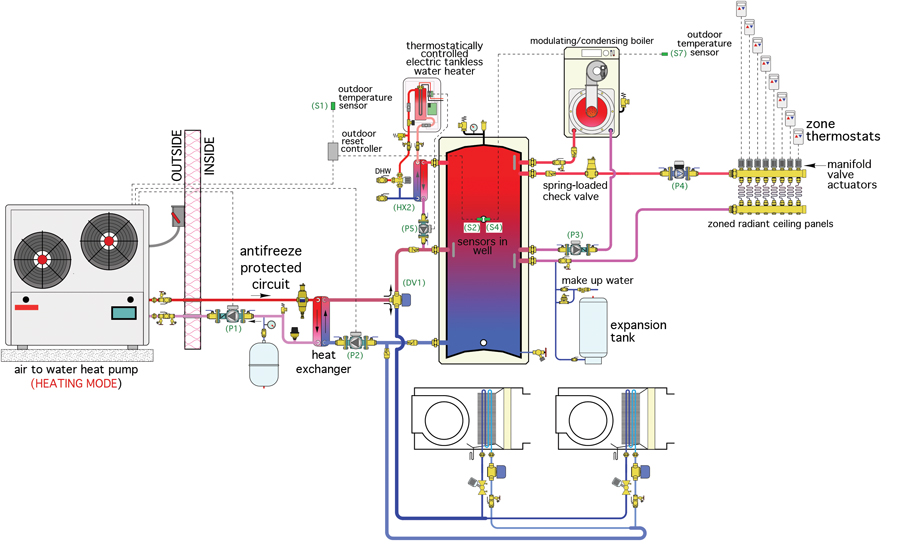
Chilled water buffer tank piping schematic.
System flow below chiller min flow 250 gpm variable primary flow at 25 system load two way valves control capacity by varying flow of water in coils per chiller system load 50 tons 176kw 50tons 176 kw primary bypass flow 250 gpm 95 l s 150 gpm 9 5 l s delta t 12 of 6 7 oc 100 gpm 44 ºf 6 3 l s 6 7 ºc 56 ºf 13 3 ºc 150.
To properly size the buffer tank calculate the systems total capacity including all piping and terminal equipment.
In this article we l be covering chilled and condenser water schematics to learn how to read them how to identify the main components and symbols as well as real world examples additionally we ll cover the purpose of the main components and different design types.
Thermal storage tanks tes blow down condensate cooler cbo boiler blow down tanks bot after coolers ac tank after coolers tac flash tanks fst non electric condensate pumps ccp heat recovery hrs electric boilers.
Cbt asme chilled water buffer tanks cbt are designed for chilled water systems with insufficient water volume capacity in relation to the chiller capacity.
Subtract that number from the chiller manufacturers recommended system capacity.
W essels company manufactures two styles of buffer tanks.
If a 100 ton chiller requires 1000 gallons of system capacity for high accuracy control and the total piping system totals only 600 gallons a 400.
Chilled water buffer tanks cbt and hot water buffer tanks hbt.


